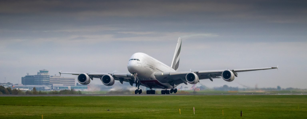
Let’s start by defining attrition—attrition is the process of reducing something’s strength or effectiveness through sustained attack or pressure. So how does attrition affect aircraft maintenance, you might ask? Well, aircraft fall under the category of heavy vehicles, which means it goes through a lot of wear and tears over the course of its life. Neither is it easy to replace the damage that has already been cost.
The five primary sources of attrition are weather, friction, overloads, heat, and vibration. These forces assert themselves in many ways on the entire structure of the aircraft during its lifespan. Persons making inspections should be familiar with the visible, measurable, or otherwise detectable effects of these forces. Each of these forces has been described below:
Weather
Local conditions such as heat, humidity, rain, wind, and snow are all the elements that affect the attrition rate of aircraft. Sometimes a combination of factors also has its own peculiar effect on different parts of the aircraft. These effects are discussed briefly in the following paragraphs.
1. Atmospheric Moisture
The moisture content of the atmosphere is directly related to the severity of oxidation found on an aircraft. Aircraft based near large bodies of water or in areas receiving heavy rainfall are more susceptible to oxidation (rusting and corrosion) than those based in arid regions. Fabric surfaces and wood structures also decay due to atmospheric conditions.
2. Oxidation
This condition is caused by the chemical combination of metal and oxygen. Oxidation causes ferrous materials such as steel or iron to rust. The oxidation of copper, aluminium and other nonferrous materials is usually known as corrosion.
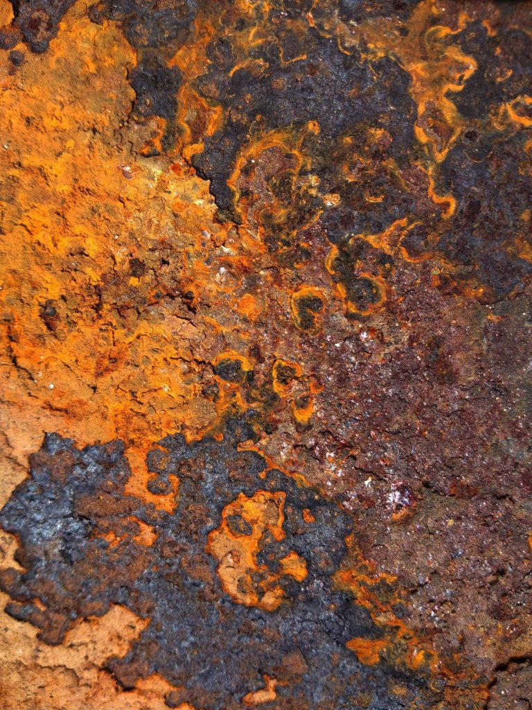
3. Rusting
Rust usually begins as a reddish discolouration on the surface, and if permitted to progress, it results in a reddish brown crustiness on the metal surface. Removal of the rusted surface layer reveals the pitting. If pitted, the part should be examined by an experienced mechanic qualified to evaluate the extent of the damage and recommend or take corrective action.
The steel tube members of an aircraft equipped with floats should be examined closely. It is possible for water to enter the interior of these members, allowing rust to form on the inside of the tubes while the exterior appears to be in good condition.
4. Corrosion
Aluminium, magnesium, and other nonferrous metals are susceptible to corrosion whenever the protective coating deteriorates. Deterioration is accelerated whenever the coating is in contact with an eroding chemical such as battery acid, insecticide, fertiliser or defoliants. Contact between two unprotected dissimilar metals sets the stage for galvanic action and corrosion, the rate of which increases significantly in the presence of moisture, especially salt water. To learn more about how to prevent corrosion, click here.
5. Decay of Wood Structure
The protective coating on wood structures usually consists of high-grade varnish or some type of transparent enamel. A good coating will have a hard glossy appearance; whenever and wherever the protective coating deteriorates, decay will start.
Weathering of the structure is first indicated by a dull appearing surface, which means that the protective film has broken down. Be especially alert to wooden components subject to the collection of moisture and/ or poor ventilation.
6. Decay of Fabric
The decay of fabric is somewhat similar to the decay of wood. If exposed to the elements, fabric absorbs moisture and other harmful substances unless it is protected by several applications of cellulose nitrate or cellulose acetate, liquids commonly known as “dope.” When “dope” is applied, it acts to tighten the fabric and produces a hard, smooth, opaque finish. In time, this finish becomes brittle and develops cracks which expose the material to the harmful effects of ultraviolet light, dirt, oil, and mildew. As a result, the strength of the fabric decreases to below minimum and is no longer airworthy.
Friction
Friction is described as the resistance to relative motion between two bodies in contact. Like any machine, the aircraft develops friction in hundreds of moving parts. The effect of friction on the plane and its components is known as wear. Wear cannot be prevented, but steps can be taken to deter its ultimate effects on the aircraft’s airworthiness by proper lubrication, alignment of moving parts, and cleanliness. To better understand inspection techniques, the terms used to describe the various conditions of wear due to friction must be understood. They are as follows:
1. Abrasion
A form of wear caused by the presence of an abrasive substance between two moving parts. In the flight control system, the possibility of abrasion can be detected by a gritty, grinding sensation noticeable during operation. Landing gear joints subjected to abrasion may exhibit an uneven jerky action when in motion. Usually, a black gritty substance can be noticed at any joint subjected to abrasion.
2. Burnishing
Burnishing is polishing a surface by sliding contact with another smooth, harder metallic surface. Usually, there is no displacement or removal of metal. Burnishing is probably the least serious of friction-caused problems; however, it should be very closely monitored. It can be considered a warning of an impending more serious condition-galling discussed later.
3. Chafing
Chafing is the wear between two parts caused by the rubbing, sliding, or bumping of one on the other. The term typically describes the wear between parts not generally in contact. Chafed fabric, wood, or metal can be detected easily since chafing usually marks one or both parts involved. Metal parts, when chafed, show a bright area where contact has been made.
Aluminium parts normally display a black or dark grey residue around the point of chafing. The simplest method of inspecting for chafing is carefully checking cables, wires, tubes, etc., wherever they are in close proximity to another part or when they are mounted to permit motion.
4. Cutting
Results in cuts or grooves in the worn part. The cause of cutting is similar to chafing, except that a sharp edge is in contact instead of a smooth surface.

5. Dent
Dent is an indentation in a surface produced by an object striking with force. The areas surrounding the indentation will usually be slightly upset. Areas especially susceptible to dent damage are the propeller, spinner, nose contour of the engine cowling, nose cone of the fuselage, and the leading edges of wings, horizontal and vertical stabilisers.
6. Elongation
Elongation is the term used to describe the egg-shaped wear of a bearing surface around a bolt, hinge pin, clevis pin, etc. It results in looseness in one plane of motion greater than that o:f the other planes. Flight control surface hinges, engine control rod ends, flight control push-pull rod ends, bellcrank ends, cable clevis ends, and similar parts are particularly susceptible to this type of wear.
7. Erosion
Erosion is the metal loss from the surface by the mechanical action of foreign materials, such as fine sand or water. The eroded area will be rough and may be lined in the direction in which the foreign material moved relative to the surface. Aircraft operated from unimproved airports are particularly susceptible to erosion, primarily on propellers, landing gear, cowling, and leading edges of wings and stabilisers.
8. Galling
Galling is the metal surface’s breakdown (or buildup) due to excessive friction between two parts having relative motion. Particles of the softer metal are torn loose and “welded” to the harder metal. Galling quite often begins as burnishing.
9. Gouge
A gouge usually involves material loss but may be largely the displacement of material and results from contact with foreign material under heavy pressure.
10. Scratch
A scratch is a slight tear or a break in the material surface from light, momentary contact with foreign material or object.
11. Score
A score is a deeper (than a scratch) tear or a break in the metal surface from contact under pressure. It may show discolouration from the temperature produced by friction. The term is normally used to describe conditions on parts designed to run together; i.e., a worn bearing might score the shaft.
12. Tear
A tear is a discontinuity which has progressed through the full thickness of the material.
Overloads
Aircraft are designed to absorb the loads imposed during regular operation and accept a certain amount of overload. Excessive loads, however, result in failure or deformation of the structure. This deformation may be slight or prominent, but it is usually visible. In any case, it can be detected and classified by certain appearances peculiar to the type of overload applied.
1. Tension
When a load is applied at either or both ends of an item, tending to pull it apart, it is loaded in tension. Overloads due to tension usually occur after a hard landing, taxiing on a rough field, or during a flight in very turbulent air. After a hard landing, all attachment fittings should be examined for tension failures or deformation. Failure is indicated by attachment fittings which show signs of pulling away from fuselage structure or failure in a welded area, and bolt holes which are elongated or torn. Welds are particularly subject to failure under tension loads and should be closely inspected.
2. Compression
A part subject to compression loads tends to fail (bulge) at the weakest point in overall length or span, at right angles to the application of the overload.
Compression failures are usually found after a hard landing, flight through turbulent air, or an accident and affect the same areas referenced under tension in the previous paragraphs. A bulge is indicative of compression failure; however, it is not always noticeable. A break in the protective paint coating may be present in this event. Sheet metal and extruded members will show some form of distortion when damaged by compression. In long members such as wing struts, compression may be first evidenced by what appears to be a bow or bend in the member.
3. Torsion
Torsion is a twisting force that tends to turn one end of a part about a longitudinal axis while the other end is held fast or turned in an opposite direction. Wheels caught in frozen ruts during a landing will tend to twist the landing gear members. Severe air loads imposed during abnormal flight manoeuvres or flight through turbulent air may twist the control surfaces or other components. Improper rigging adjustments to wings and tail surfaces may also cause twisting of these components.
4. Shear
An action or stress resulting from forces applied so as to cause a portion of a part to move relative to another portion in a direction parallel to the direction of the force. This action is normally found in tools such as bolt cutters or sheet metal shears, which apply the force and shear the material being worked on.
When an overload is applied, the part having the least resistance to the force will be the first to fail. For this reason, bolts, rivets, and clevis pins should be examined for signs of failure.
5. Bending
Bending is a force or combination of forces that will cause a rigid member to curve or bow away from a straight line. Overloads which cause bending are usually the result of abnormal landing and flight loads or improper ground handling of the aircraft. Bent components will result from the following practices:
- Stepping or pushing on the lift or other struts
- Lifting the plane by the stabiliser
- Jacking or placing supports under longerons
- Overloading cabin or baggage compartments
- Exceeding turn limitations of the nose steering mechanism
Heat
The principal source of heat affecting the aircraft is the powerplant. From the standpoint of inspection, we are interested in two heating methods, direct and indirect, both normally the result of engine operation. Direct heat usually originates from leaking exhaust gases. Indirect heat is that radiated from any hot system or component.
1. Direct Heat
Leaks in components of the exhaust system may permit carbon monoxide to enter the cabin heating system. More severe leaks or failures of exhaust system components may allow flames to escape into surrounding areas with disastrous results.
To forestall serious hazards, the exhaust pipes, clamps, bolts, braces, and welds should be examined at frequent intervals. Exhaust gaskets must be in good condition. The nuts holding the exhaust pipe or manifold to the cylinder must be properly torqued and safetied. Loose exhaust pipe bracing allows the pipe to vibrate, causes failure at the welds, and leaks from the flange surfaces. Heater muffs or shrouds should be removed to enable the inspection of the exhaust system components.
2. Indirect Heat
Indirect heat radiated or conducted from the engine is carried off by the action of the air stream passing through the cowling. If the air stream cannot carry the heat away, the resulting high temperatures are harmful to the engine and may cause the failure of accessories or other parts of the powerplant assembly. Excessive indirect heat may be indicated by one or more of the following:
1) High oil temperature.
2) High cylinder head temperature.
3) Blistering of the paint covering adjacent parts within the engine compartment.
4) An odour of burned oil or hot rubber during or after engine operation.
5) Auto-ignition upon shutdown of the engine (engine tries to continue functioning).
Vibration
Vibration is the source of many malfunctions and defects that occur throughout the life ·of the aircraft. Not only will vibration affect parts that are loose or poorly installed, but it will also accelerate wear and cause the ultimate failure of others. There are two types of vibration in aircraft operation; low frequency and high frequency.
1. Low-frequency
Low-frequency vibration is usually caused by a malfunctioning powerplant or propeller, worn engine mounting pads, looseness of the aircraft structure, or improper rigging. The problem causing vibration should be corrected as soon as discovered since it will cause abnormal wear between moving parts of the aircraft and may induce failure in any other aircraft parts.
2. High-Frequency
High-frequency vibration is caused by inherent vibration characteristics of the rotating masses in the engine and propeller. It can also be caused by aerodynamic forces acting through the propeller or engine firing impulses. When harmful vibration frequencies are found, placards are installed indicating the engine operating ranges which must be avoided.
3. Factors of Vibration Damage
The factors of vibration damage can be grouped into three categories: fatigue, excessive clearance, and poor installation. These points should be considered when inspecting for the effects of vibration.
A. Fatigue
Fatigue is the weakening and/or eventual failure o:f a member due to the cumulative effects of repetitive loads, which cause a change in the molecular structure of the part. Fatigue itself cannot be detected or measured while it is taking place except, possibly, under laboratory conditions. Its effects are usually made known by the ultimate failure of a part. The best prevention against fatigue damage is to maintain a smoothly running power plant. In addition, control excessive or abnormal looseness in other aircraft components by good maintenance practices, particularly engine mounting pads ·s designed to isolate and absorb vibration.
B. Excessive Clearance
Excessive clearances accelerate the wear rates of all components in which they exist and can contribute to the initiation of flutter. Flutter is an aerodynamic function wherein oscillating high loads are imposed on the affected movable surfaces and can result in rapid fatigue failure of critical areas, such as control surface hinge fittings and attachments. Wear rates are extremely high during flutter. It is very important to maintain clearance within the limit established by the manufacturer.
C. Installation
Installation is the proper arrangement of the various parts in relation to each other. A fuel line, for example, may have sufficient clearance relative to another part while at rest, yet under vibration, it may move and make contact with the other part and become chafed or cut.
Ignition or electrical cables in contact with each other may appear perfectly rigid during regular operation, but during periods of vibration, they may rub together and wear through the protective casings. Every part of the aircraft should be carefully examined for signs of chafing or cutting. If the vibration has gone uncorrected for a time, all nuts, bolts, clamps, etc., should be checked for proper security.
4. Propeller Vibration
Propellers have inherent vibration characteristics which are not usually harmful but can induce fatigue and, in time, cause failure of parts essential to the airworthiness of the aircraft. This is one reason why periodic inspection of the aircraft is essential.
Conclusion
The effects of forces of attrition on aviation MRO are severely damaging yet absolutely preventable. The steps necessary to ensure the longevity of aircraft equipment are to be aware of the warning signs, use high-quality products, and keep in touch with skilled technicians who can help you in times of need. Thankfully we offer all three (products and services) at ORAPI, and we are always ready to help. To learn more about our product recommendations and services, click on the button below.
Complete list of Aircraft MRO + Cleaning Products under 1 Download